- 您现在的位置:买卖IC网 > Sheet目录985 > ISLA224IR72EV1Z (Intersil)BOARD EVALUATION FOR ISLA224P
�� �
�
�ISLA224P�
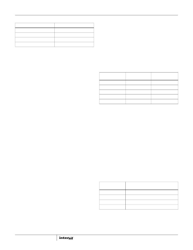
�TABLE� 4.� BYTE� TRANSFER� SELECTION�
�ADDRESS� 0X20:� OFFSET_COARSE_ADC0�
�[W1:W0]�
�00�
�01�
�10�
�11�
�BYTES� TRANSFERRED�
�1�
�2�
�3�
�4� or� more�
�ADDRESS� 0X21:� OFFSET_FINE_ADC0�
�The� input� offset� of� the� A/D� core� can� be� adjusted� in� fine� and�
�coarse� steps.� Both� adjustments� are� made� via� an� 8-bit� word� as�
�detailed� in� Table� 5.� The� data� format� is� twos� complement.�
�The� default� value� of� each� register� will� be� the� result� of� the�
�self-calibration� after� initial� power-up.� If� a� register� is� to� be�
�Figures� 42� and� 43� illustrate� the� timing� relationships� for� 2-byte�
�and� N-byte� transfers,� respectively.� The� operation� for� a� 3-byte�
�transfer� can� be� inferred� from� these� diagrams.�
�SPI� Configuration�
�ADDRESS� 0X00:� CHIP_PORT_CONFIG�
�incremented� or� decremented,� the� user� should� first� read� the�
�register� value� then� write� the� incremented� or� decremented� value�
�back� to� the� same� register.� Bit� 0� in� register� 0xFE� must� be� set� high�
�to� enable� updates� written� to� 0x20� and� 0x21� to� be� used� by� the�
�ADC� (see� description� for� 0xFE).�
�TABLE� 5.� OFFSET� ADJUSTMENTS�
�Bit� ordering� and� SPI� reset� are� controlled� by� this� register.� Bit� order�
�can� be� selected� as� MSB� to� LSB� (MSB� first)� or� LSB� to� MSB� (LSB�
�first)� to� accommodate� various� micro� controllers.�
�Bit� 7� SDO� Active�
�Bit� 6� LSB� First�
�Setting� this� bit� high� configures� the� SPI� to� interpret� serial� data� as�
�arriving� in� LSB� to� MSB� order.�
�PARAMETER�
�Steps�
�–Full� Scale� (0x00)�
�Mid–Scale� (0x80)�
�+Full� Scale� (0xFF)�
�Nominal� Step� Size�
�0x20[7:0]�
�COARSE� OFFSET�
�255�
�-133LSB� (-47mV)�
�0.0LSB� (0.0mV)�
�+133LSB� (+47mV)�
�1.04LSB� (0.37mV)�
�0x21[7:0]�
�FINE� OFFSET�
�255�
�-5LSB� (-1.75mV)�
�0.0LSB�
�+5LSB� (+1.75mV)�
�0.04LSB� (0.014mV)�
�Bit� 5� Soft� Reset�
�Setting� this� bit� high� resets� all� SPI� registers� to� default� values.�
�Bit� 4� Reserved�
�This� bit� should� always� be� set� high.�
�Bits� 3:0�
�These� bits� should� always� mirror� bits� 4:7� to� avoid� ambiguity� in� bit�
�ordering.�
�ADDRESS� 0X02:� BURST_END�
�If� a� series� of� sequential� registers� are� to� be� set,� burst� mode� can�
�improve� throughput� by� eliminating� redundant� addressing.� The�
�burst� is� ended� by� pulling� the� CSB� pin� high.� Setting� the� burst_end�
�address� determines� the� end� of� the� transfer.� During� a� write�
�operation,� the� user� must� be� cautious� to� transmit� the� correct�
�number� of� bytes� based� on� the� starting� and� ending� addresses.�
�Bits� 7:0� Burst� End� Address�
�This� register� value� determines� the� ending� address� of� the� burst�
�data.�
�ADDRESS� 0X22:� GAIN_COARSE_ADC0�
�ADDRESS� 0X23:� GAIN_MEDIUM_ADC0�
�ADDRESS� 0X24:� GAIN_FINE_ADC0�
�Gain� of� the� A/D� core� can� be� adjusted� in� coarse,� medium� and� fine�
�steps.� Coarse� gain� is� a� 4-bit� adjustment� while� medium� and� fine�
�are� 8-bit.� Multiple� Coarse� Gain� Bits� can� be� set� for� a� total�
�adjustment� range� of� ±4.2%.� (‘0011’� ?� -4.2%� and� ‘1100’� ?� +4.2%)�
�It� is� recommended� to� use� one� of� the� coarse� gain� settings� (-4.2%,�
�-2.8%,� -1.4%,� 0,� 1.4%,� 2.8%,� 4.2%)� and� fine-tune� the� gain� using� the�
�registers� at� 0x0023� and� 0x24.�
�The� default� value� of� each� register� will� be� the� result� of� the�
�self-calibration� after� initial� power-up.� If� a� register� is� to� be�
�incremented� or� decremented,� the� user� should� first� read� the�
�register� value� then� write� the� incremented� or� decremented� value�
�back� to� the� same� register.� Bit� 0� in� register� 0xFE� must� be� set� high�
�to� enable� updates� written� to� 0x23� and� 0x24� to� be� used� by� the�
�ADC� (see� description� for� 0xFE).�
�TABLE� 6.� COARSE� GAIN� ADJUSTMENT�
�Device� Information�
�ADDRESS� 0X08:� CHIP_ID�
�ADDRESS� 0X09:� CHIP_VERSION�
�The� generic� die� identifier� and� a� revision� number,� respectively,� can�
�be� read� from� these� two� registers.�
�Device� Configuration/Control�
�A� common� SPI� map,� which� can� accommodate� single-channel� or�
�multi-channel� devices,� is� used� for� all� Intersil� A/D� products.�
�25�
�0x22[3:0]� core� 0�
�0x26[3:0]� core� 1�
�Bit3�
�Bit2�
�Bit1�
�Bit0�
�NOMINAL� COARSE� GAIN� ADJUST�
�(%)�
�+2.8�
�+1.4�
�-2.8�
�-1.4�
�FN7570.1�
�November� 30,� 2012�
�发布紧急采购,3分钟左右您将得到回复。
相关PDF资料
ISPTPKIT
SCREW KIT TAMPER RESISTANT 9PCS
ITCSN-0400-25-U
HEATSHRINK ITCSN 2/5" X 25'
JC2AF-TM-DC24V-F
RELAY GEN PURPOSE DPST 10A 24V
JJM1A-12V
RELAY AUTOMOTIVE SPST 20A 12V
JM1AN-ZTM-DC5V-F
RELAY GEN PURPOSE SPST 20A 5V
JQ1P-18V-F
RELAY GEN PURPOSE SPDT 10A 18V
JS1-F-6V-F
RELAY GEN PURPOSE SPDT 10A 6V
JSM1-9V-5
RELAY AUTOMOTIVE SPDT 15A 9V
相关代理商/技术参数
ISLA224P
制造商:INTERSIL 制造商全称:Intersil Corporation 功能描述:Dual 14-Bit, 250MSPS/200MSPS/130MSPS ADC
ISLA224P12
制造商:INTERSIL 制造商全称:Intersil Corporation 功能描述:High Performance Dual 14-Bit, 125MSPS ADC
ISLA224P12IRZ
制造商:Intersil Corporation 功能描述:DUAL 14-BIT 125MSPS UNBUFFERED INPUT, 72-PIN - Trays 制造商:Intersil Corporation 功能描述:IC ADC 14BIT SPI/SRL 125M 48QFN 制造商:Intersil 功能描述:Dual 14-Bit 125MSPS Unbuffered Input, 72
ISLA224P13
制造商:INTERSIL 制造商全称:Intersil Corporation 功能描述:Dual 14-Bit, 250MSPS/200MSPS/130MSPS ADC
ISLA224P13IRZ
制造商:Intersil Corporation 功能描述:DUAL 14-BIT 130MSPS UNBUFFERED INPUT, 72-PIN - Trays 制造商:Intersil Corporation 功能描述:IC ADC 14BIT SRL/SPI 72QFN 制造商:Intersil 功能描述:DL 14-BIT 130MSPS UNBUFRED INPUT 72PIN
ISLA224P20
制造商:INTERSIL 制造商全称:Intersil Corporation 功能描述:Dual 14-Bit, 250MSPS/200MSPS/130MSPS ADC
ISLA224P20IRZ
制造商:Intersil Corporation 功能描述:DUAL 14-BIT 200MSPS UNBUFFERED INPUT, 72-PIN - Trays 制造商:Intersil Corporation 功能描述:IC ADC 14BIT SRL/SPI 72QFN 制造商:Intersil 功能描述:DL 14-BIT 200MSPS UNBUFRED INPUT 72PIN 制造商:Intersil Corporation 功能描述:IC, ADC, 14BIT; Resolution (Bits):14bit; Sampling Rate:200MSPS; Supply Voltage Type:Single; Supply Voltage Min:1.7V; Supply Voltage Max:1.9V; Supply Current:375mA; Digital IC Case Style:QFN; No. of Pins:72; Data Interface:SPI ;RoHS Compliant: Yes
ISLA224P25
制造商:INTERSIL 制造商全称:Intersil Corporation 功能描述:Dual 14-Bit, 250MSPS/200MSPS/130MSPS ADC